Medical power supplies rarely attract attention until a monitor resets, an infusion pump stops, or an alarm goes silent. That quiet failure can become a clinical risk within seconds. The World Health Organization’s Global Patient Safety Report 2024 states that about one in ten patients experiences harm during healthcare delivery. More than half of this harm is considered preventable. Not every event is caused by electricity, but unstable voltage, leakage current, poor isolation, and weak backup design can amplify harm. Safety is never decorative.
To Improve safety performance of medical power supply devices, engineers and procurement teams need evidence beyond a certificate. IEC 60601-1 defines essential safety and performance requirements for medical electrical equipment. IEC 60601-1-2 addresses electromagnetic compatibility and immunity to hospital disturbances. These standards matter at the bedside. Yet laboratory compliance does not guarantee safe behavior during installation, cleaning, aging, overload, or emergency transfer. The U.S. FDA’s MAUDE database also demonstrates why post-market feedback deserves serious attention. Field reports can reveal recurring failures that controlled testing misses.
A dependable assessment should examine creepage distances, earth continuity, thermal rise, transient response, battery autonomy, and alarm behavior. It should also trace suppliers, firmware changes, repair quality, and maintenance intervals. Small details become visible under pressure. An overloaded socket, loose connector, or depleted backup battery may look minor during inspection. At 3 a.m., they are not minor. Manufacturers should combine risk management, verification testing, production controls, and honest incident review. Healthcare providers must validate the complete system, not only the power module. Safety performance can improve, but perfection is an unsafe assumption. Recommendations may require revision as devices, wards, and evidence change.
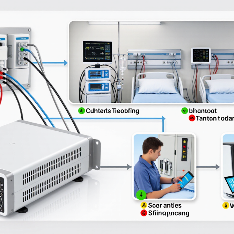
Improving medical power supply safety starts with understanding the requirements behind IEC 60601-1. The standard evaluates protection against electric shock, abnormal operation, and single-fault conditions. Designers must separate operator protection from patient protection. A hospital bed, infusion pump, and diagnostic monitor may therefore need different insulation strategies. Creepage, clearance, earth continuity, and leakage current require measurement, not assumption. In some patient-connected circuits, two Means of Patient Protection may be necessary.
The World Health Organization’s Global Patient Safety Action Plan 2021–2030 reports that about one in ten patients experiences harm during healthcare delivery. More than half of this harm is considered preventable. The report does not attribute these events only to electrical failures. Still, unstable voltage, insulation breakdown, and poor grounding can turn a small defect into a clinical risk. Testing should cover normal operation, overload, humidity, temperature changes, and realistic cable movement. Short tests are not enough.
IEC 60601-1-2 also addresses electromagnetic compatibility. A power supply can remain electrically safe yet disrupt nearby monitoring equipment. That possibility is often underestimated. Engineers should document immunity tests, leakage-current results, component derating, and production traceability. Service teams need clear inspection points, especially around connectors and damaged insulation. I have seen checklists treated as proof of safety. They are not. Real safety depends on repeatable testing, honest fault analysis, and reviewing failures before they become incidents.
Medical devices face electrical and environmental risks that can remain hidden during normal operation. A power supply may deliver stable voltage in a laboratory, yet behave differently beside a surgical motor or imaging system. Leakage current, insulation damage, poor grounding, and sudden voltage dips deserve careful attention. A loose connector can create intermittent faults. These faults are difficult to reproduce.
Environmental conditions add another layer of risk. Moisture may enter through a damaged enclosure or poorly sealed cable opening. Cleaning chemicals can weaken plastic surfaces over time. Heat near an examination lamp may raise internal temperatures beyond expected limits. Dust can block ventilation and increase stress on capacitors. Technicians should record temperature, humidity, cleaning exposure, vibration, and installation clearance during risk assessments.
Safety verification should follow recognized medical electrical equipment requirements, including insulation, dielectric strength, protective earth, and abnormal-condition testing. Test results need traceable instruments, defined acceptance limits, and clear maintenance records. A visual check is useful, but it cannot replace electrical measurement. Nor can a passed factory test guarantee safe field performance.
Small oversights matter. A cable may pass inspection but fail after repeated bending. A grounding path may appear secure while corrosion grows underneath. Engineers should review real use conditions, not only ideal specifications. This process is not perfect, and risk assessments may miss unusual combinations of heat, moisture, and load. Regular reassessment helps expose those gaps.
Reliable medical power begins with component selection, not emergency repair. The WHO and World Bank report Energizing Health (2023) found that hundreds of millions of people rely on health facilities without dependable electricity. Voltage dips, surges, and brief interruptions can stop monitoring, corrupt stored data, or silence alarms. Select components with documented safety margins, traceable test records, and stable performance across temperature and load changes. Medical-grade isolation, appropriately rated fuses, thermal cutoffs, and reinforced insulation should support the design. IEC 60601-1 also requires careful control of leakage current, creepage, and clearance distances.
Protective circuits must respond without creating a second hazard. Use surge suppressors, overvoltage protection, current limiting, and short-circuit isolation. A watchdog can detect a frozen controller and trigger a controlled recovery. Battery systems need protection against overcharge, deep discharge, overheating, and cell imbalance. Test the complete power path, not only individual parts. IEC 60601-1-2 testing is useful for assessing electromagnetic disturbances. However, laboratory compliance does not guarantee perfect field behavior. Cable routing, cleaning fluids, aging connectors, and repeated sterilization can expose overlooked weaknesses. Risk analysis under ISO 14971 should connect each failure mode with a measurable control.
Tips: Keep protection close to the entry point. Record every component revision. Test brownouts with realistic loads. Inspect connectors after repeated cycling. Do not assume a backup battery solves interruption risk. It may fail silently. Field feedback should challenge the original design, even when certification has already been achieved.
Selecting Reliable Components and Protective Circuit Designs
This chart presents commonly referenced maximum leakage-current limits from IEC 60601-1: touch current is limited to 100 µA in normal condition and 500 µA in single-fault condition, while patient leakage limits are 100/500 µA for Type B and BF applied parts and 10/50 µA for Type CF applied parts. Actual compliance depends on the applicable edition, measurement network, equipment classification, insulation system, and operating condition. Use certified safety components, correctly rated fuses, surge protection, reinforced isolation, and verified creepage and clearance distances to maintain these limits throughout the product life cycle.
Medical power safety begins with controlling where current can travel. Isolation separates patient-connected circuits from hazardous mains voltage. Use reinforced insulation or a suitably rated isolation transformer. Verify dielectric strength, creepage, and clearance during design reviews. A 2.5-millimeter gap is not automatically safe. Working voltage and pollution conditions also matter. IEC 60601-1 offers useful requirements, but testing must match the actual equipment.
Grounding gives fault current a predictable path away from users. Bond exposed conductive parts to protective earth with short, low-impedance conductors. Check continuity after assembly, not only in drawings. A loose terminal can turn a metal enclosure into a shock hazard. In mobile equipment, ground integrity may change when cables flex, connectors age, or paint enters a bonding joint. That detail matters. Add overcurrent protection for normal inrush and fault conditions. Fuses and circuit breakers should interrupt faults before conductors overheat. Oversized protection may keep equipment running while insulation quietly fails. Too-small protection can nuisance-trip during startup. Measure both.
A practical verification plan combines visual inspection, earth-leakage tests, insulation tests, and functional fault simulations. Record test equipment, calibration status, ambient conditions, and operator decisions. Engineers should review abnormal results instead of dismissing them as noise. A clean prototype can still fail after repeated connector movement. That failure is useful. It may expose a weak grounding assumption. Design margins should reflect service conditions, cleaning cycles, and foreseeable misuse. Some uncertainty remains. Document it, then test the weakest point again.
How to Improve Medical Power Supply Safety Performance?
Testing, monitoring, and maintenance must work as one safety process. IEC 60601-1 addresses basic safety and essential performance for medical electrical equipment. IEC 62353 supports recurrent testing and testing after repairs. Technicians should verify protective earth continuity, insulation resistance, leakage current, output voltage, and battery condition. Record the results beside the asset number, test date, operator, and acceptance limit. A paper pass is not enough.
Continuous monitoring adds another layer. Watch voltage drift, overload events, abnormal temperature, battery impedance, and alarm response. A simple dashboard can expose repeated faults before a patient-care interruption occurs. ECRI’s 2024 Top 10 Health Technology Hazards highlights risks linked to poor battery management and device readiness. That warning matters in treatment rooms, where an unused backup may look healthy but fail under load. Test it under realistic demand.
Maintenance intervals should follow risk, usage, manufacturer instructions, and local requirements. WHO’s Global Patient Safety Action Plan reports that about one in ten patients experiences harm in healthcare, with more than half considered preventable. Power systems are only one contributor, but they deserve disciplined attention. In field inspections, loose connectors and overdue batteries are easy to miss. That is our weak point. A clean test result can still hide poor housekeeping, unclear ownership, or rushed documentation. Review failures monthly, train staff with practical scenarios, and challenge any limit that no longer reflects real clinical use.
| Safety Dimension | Key Performance Indicator | Recommended Test or Monitoring Method | Typical Acceptance Basis | Suggested Frequency | Corrective Action |
|---|---|---|---|---|---|
| Electrical Shock Protection | Protective earth continuity and leakage current | Use calibrated electrical safety equipment to measure protective conductor resistance, earth leakage, touch current, and patient leakage current. | Limits specified by the equipment classification, applied part type, installation configuration, and the applicable edition of IEC 60601-1 or IEC 62353. | After repair or relocation; periodically according to the healthcare facility risk assessment. | Remove from service, identify the fault, repair or replace the affected component, and repeat the complete safety test. |
| Output Voltage Stability | Output voltage deviation under normal and maximum rated load | Measure the output with a calibrated multimeter or power analyzer while applying no-load, typical-load, and maximum-rated-load conditions. | Must remain within the power supply and medical device specifications across the declared input-voltage and load range. | During commissioning, scheduled preventive maintenance, and after suspected voltage-related faults. | Check regulation circuitry, connectors, wiring, and load conditions; replace failed parts and verify performance again. |
| Overvoltage Protection | Response of overvoltage protection and absence of unsafe output overshoot | Review design verification results and use an oscilloscope or power analyzer during controlled fault and transient tests. | Protection must limit the output to the device-defined safe range and recover or shut down as specified by the risk analysis. | At design validation and after circuit or firmware changes; functional checks during service testing. | Investigate the sensing and switching circuits, document the failure mode, and repeat fault-condition verification. |
| Overcurrent and Short-Circuit Protection | Current-limiting accuracy and safe shutdown or recovery | Apply controlled overload and short-circuit conditions using an approved test setup; monitor current, voltage, temperature, and recovery behavior. | The protection function must prevent hazardous overheating, fire, component damage, and unsafe output conditions. | During design verification and after replacement of protection components; visual checks during maintenance. | Replace damaged fuses or protection devices only with approved ratings; determine and correct the underlying cause. |
| Insulation Integrity | Insulation resistance and dielectric withstand performance | Perform insulation resistance and dielectric strength tests using procedures suitable for the device design and insulation system. | Test voltage, duration, and limits must follow the applicable safety standard, product specification, and risk controls. | During type testing, production testing, after major repair, and when insulation damage is suspected. | Stop use if breakdown, arcing, or unacceptable leakage is detected; replace damaged insulation or assemblies. |
| Thermal Safety | Component, enclosure, and accessible-surface temperature | Measure temperatures at rated load and under abnormal conditions using thermocouples or a calibrated thermal measurement system. | Temperatures must remain within applicable limits for components, materials, operators, and patients. | During design validation, after ventilation changes, and during preventive maintenance. | Clean vents, restore airflow, inspect fans and thermal sensors, reduce overload, or replace overheating components. |
| Power Quality and Electromagnetic Compatibility | Immunity to voltage dips, interruptions, surges, and conducted or radiated disturbances | Perform applicable immunity and emissions tests using the test levels and methods defined by IEC 60601-1-2 and the device risk assessment. | Essential performance must be maintained, or the equipment must recover safely without creating unacceptable risk. | Before market release, after significant design changes, and when interference incidents occur. | Improve filtering, shielding, grounding, cable routing, or transient protection; repeat EMC verification. |
| Battery and Backup Power | Backup runtime, charging performance, battery condition, and alarm operation | Check battery voltage, charging current, capacity or runtime, connection integrity, and low-battery or failure alarms. | Runtime and alarm behavior must meet the medical device specification and the facility's continuity-of-care requirements. | Functional checks at scheduled intervals; full capacity testing according to the battery-management program. | Replace batteries showing reduced capacity, swelling, leakage, excessive heating, or failed alarms. |
| Mechanical and Environmental Condition | Enclosure integrity, connector condition, ingress protection, vibration, dust, and moisture exposure | Perform visual inspection, connector inspection, cleaning verification, and environmental checks appropriate to the installation location. | No exposed hazardous parts, cracked insulation, loose connections, blocked ventilation, or environmental condition outside the rated range. | Before use, during preventive maintenance, and after transport, impact, liquid ingress, or abnormal exposure. | Quarantine damaged equipment, clean or repair it, and complete electrical safety testing before return to service. |
| Alarm and Fail-Safe Behavior | Detection, indication, and response to power failure or abnormal output | Simulate defined power-fault conditions and verify visual, audible, remote, and system-level alarms. | Alarms must be recognizable, correctly prioritized, and consistent with the device risk-management file and operating instructions. | During commissioning, preventive maintenance, and after alarm-related service work. | Correct sensor, software, wiring, or notification faults; repeat the complete alarm and recovery test. |
| Preventive Maintenance and Documentation | Test completion rate, calibration status, failure trends, and traceability of service records | Maintain an asset register containing equipment identification, test results, calibration status, defects, repairs, and release authorization. | All required tests must be completed with calibrated instruments, documented results, clear pass/fail decisions, and authorized sign-off. | Review after every service event and at least annually as part of the medical equipment safety program. | Escalate overdue tests or recurring failures, perform root-cause analysis, and revise maintenance intervals based on risk and failure data. |
Note: Acceptance limits and test intervals must be determined from the applicable medical electrical equipment standards, manufacturer specifications, equipment classification, intended use, and documented risk assessment.
Nearby motors or imaging equipment may cause voltage dips, noise, or intermittent faults. Laboratory stability proves little. Real installation conditions matter.
Check leakage current, insulation damage, grounding, loose connectors, and unexpected voltage drops. A connector may look secure but fail during movement.
Moisture can enter through damaged seals or cable openings. Cleaning chemicals may weaken plastic surfaces after repeated exposure. Small damage grows.
Record temperature, humidity, cleaning exposure, vibration, dust, and installation clearance. Heat near a lamp can raise internal temperatures quickly.
Isolation separates patient-connected circuits from hazardous mains voltage. Use suitable reinforced insulation or an appropriately rated isolation transformer.
No. Safe spacing depends on working voltage and pollution conditions. A 2.5-millimeter gap is not automatically sufficient.
Bond exposed conductive parts to protective earth with short, low-impedance conductors. Check continuity after assembly. Paint or corrosion can weaken the connection.
Protection must handle normal startup current and interrupt faults before conductors overheat. Oversized protection may hide insulation failure. Undersized protection may trip unnecessarily.
No. Combine visual checks with leakage, insulation, continuity, dielectric, and fault-simulation tests. Record instruments, calibration, conditions, and decisions.
Reassess after repeated bending, connector movement, cleaning cycles, repairs, or installation changes. Testing is not perfect. Unexpected heat and moisture combinations can remain hidden.
Improving the safety performance of medical power supply devices requires a systematic approach that begins with understanding applicable medical electrical safety requirements. Designers should identify potential electrical and environmental risks, including electric shock, leakage current, short circuits, overheating, moisture, vibration, and electromagnetic interference. These risks must be evaluated according to the device’s operating conditions and intended patient contact.
Reliable components, protective circuit designs, appropriate isolation, effective grounding, and properly rated overcurrent protection are essential for stable and safe operation. Safety performance should also be verified through insulation, leakage current, dielectric strength, temperature, overload, and abnormal-condition testing. Continuous monitoring can help detect faults before they affect patients or equipment, while scheduled inspections, preventive maintenance, and timely replacement of aging components help preserve long-term reliability. By combining careful design, rigorous testing, and ongoing maintenance, manufacturers can Improve safety performance of medical power supply devices and support safer healthcare environments.

JDI Power Supply